Yamaha 8HP Outboard Water Pump Service
May 16th, 2010 | by Marilyn | Published in Maintenance and Repairs | 14 Comments
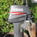
Our dinghy came with a Yamaha 8 HP 2-stroke outboard (1999 model 8MSHX). We we started it up for the first time, there wasn’t any water coming out the telltale hole so we decided it was time to service the water pump. I’ll describe the process below – but let me first say that servicing the water pump did not solve the no-telltale-water-flow problem.
It appears this used motor hasn’t had the chambers properly flushed with fresh water after use in some sandy saltwater conditions. After servicing the water pump and seeing no change in the telltale flow, we took off the thermostat plate and discovered loads of sand and gunk. I’ll report about that thermostat area and how we did the final cleaning in another post.
Back to the procedure for servicing the water pump. We figured out how to do this based on the dodgy Yamaha service manual (LIT-18616-01-64). That manual is extremely brief on procedures but it does have nice exploded views and all torque settings. You can also see the exploded views from part sellers, such as www.boats.net. I’ll give you the proper torque settings here. I wouldn’t recommend splashing out on the manual. This is what we did (there are photos that illustrate some of the steps in the gallery at the bottom of this post):
1. Buy a water pump kit rather than just the impeller – it’s worth the few extra dollars to get new screws and insert catridge, water tube bushing, etc. We got our kit from iBoats.com. It was Sierra kit Part # 18-3460. You can also find the original Yamaha kit for a little more money if you prefer manufacturer parts.
2. Drain the oil from the lower unit of the motor, which simply means removing the drain plug at the lower part of the unit and loosen the fill plug which is a little higher and let it run out. It holds around a cup, so you don’t need a large container to catch it.
3. For safety sake and to make lower unit assembly a little easier, take off the prop. To do this,
– take out the cotter pin.
– remove the nut – it’s a normal right-hand thread. Best way to hold the shaft steady while removing the nut is to wedge a block of wood between a prop blade and the lower unit body to hold the prop steady. Don’t depend on putting it in gear to stop the prop from spinning. Our nut was almost seized and it required an impact driver to get it off.
– Pull off the washer, the prop, and the spacer.
You’ll be left with the prop shaft sticking out. Now is a good time to inspect it for wear and free play – it shouldn’t have any or else vibration will cause the seals to fail and wreak havoc on your lower unit. Also check for any fishing line or other debris wrapped around the prop shaft.
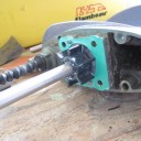
4. Now it’s time to disconnect the shift rod in the lower unit from the shifting mechanism in the upper casing. This stuff is located on the inboard side of the motor in the upper casing, behind the hinge area (see photo below). It’s best to tilt the motor up to get access to it. Also, put the motor in reverse to move the shift rod connector into a more reachable position. Make a note of how the shift rod is connected – reconnecting this later is a little tricky, so pay attention to how it looks at the start. Then, undo the bolt and nut on the shift rod connector. Realize that the nut serves as a lock nut. The side of the shift rod connector that is opposite the bolt head is also threaded, so to loosen this connection, you must first take off the nut and then turn the bolt out of the connector. Our bolt was seized and we actually ended up shearing the bolt off. We replaced it with an M6-1.0 20mm SS bolt. Clean-up these 2 shift rod connector parts, as well as the bolt and nut, and set them aside for now.
5. Remove the lower unit. To do this:
– Remove the 4 bolts that hold the lower unit to the upper casing (see photo below).
– Carefully start wiggling and prying the lower unit off. There are dowel pins and 3 slip-fit shafts, so you must pull it straight out.
Once you have it out, you will see the drive shaft (with the water pump housing around it) and the shift rod (with the rubber sleeve) sticking out.
6. Now you can dissemble the water pump. To do this:
– Remove the 4 bolts and the 2 plates.
– Pull off the water pump housing. There is a bushing in the water inlet tube portion of this housing, and there is a replacement for this in your Sierra water pump kit.
– Pull off the metal insert cartridge and the impeller. Note the orientation of the impeller blades with respect to the shaft. The drive shaft spins clockwise (when viewed from the bottom) so the impeller blades will point in the counterclockwise direction. If any impeller blades are missing, you’ll have to go searching for them in the water cavities in the power unit. Fortunately ours was still intact, though it was time for replacement because the blades were looking a little ratty and had definitely taken a set.
– Remove the woodruff key from the shaft so you can get off the outer metal plate. The bit of this key that inserts into the shaft is rounded, so just grab the exposed part of the key with a vise grips and pull straight out. Don’t lose this little piece, as the water pump kit doesn’t offer a replacement.
– Pull off the gasket and outer plate and discard.
Now you have completely disassembled the water pump. Clean up the housing as needed. It shouldn’t be worn because the insert cartridge protects it.
7. Time for reassembly using all the new parts provided in the water pump kit. To do this:
– Put on the new outer plate. There are dowel pins so it can only go on in one orientation. We smeared it with a little waterproof grease first.
– Put on the new gasket, again smeared with a little waterproof grease.
– Reinsert the original woodruff key.
– Smear the blades of the new impeller with waterproof grease, then slide it onto the shaft. Note that one face of the impeller’s bronze hub has a slot for the woodruff key and the other face does not, so there is only one orientation in which you can slide this impeller on completely. (see photo below)
– Slide the new insert cartridge onto the drive shaft. As you get to the impeller, twist the cartridge to the right and press the impeller blades to point to the left so that when in use, the impeller will spin clockwise.
– Slide the water pump housing onto the shaft. Be sure to align the hole in the water pump housing with the projection in the insert cartridge. Look at the parts, and that will make sense to you.
– If you have not already done so, replace the bushing on the water pump housing that acts as the water seal.
– Put on the metal plates on each side of the housing.
– According to Yamaha manual, apply Loctite (572 – blue) to the bolts and torque them to 11 Nm (1.1 m*kg, 8.0 Ft*Lb). This completes reassembly of the pump. (see photo below)
8. In prep for lower unit reattachment, clean the splines at the end of the drive shaft and coat them with waterproof grease. Plenty of people caution on making sure this is well lubed so that the drive shaft doesn’t seize onto the crankshaft, making lower unit removal damaging and potentially impossible.
9. Also put a little grease on the end of the water tube, which you find in the upper casing of the motor. This will slip into the water pump housing through the new bushing you have installed.
10. You are now ready for reattachment of the lower unit. When you do this, you must make sure to properly insert these 3 things:
– drive shaft into the crankshaft. This may require that you give the power unit flywheel a little turn if the splines on the drive shaft are not able to mesh with the crank shaft. You can turn the flywheel by hand.
– insert the water tube that is in the upper casing into the water seal on the pump housing;
– insert the shift rod into the upper casing. It doesn’t seem to matter what gear the motor is in at this point, but it’s probably easiest if it’s still in reverse.
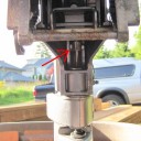
When sliding the lower unit back onto the upper casing, do not force anything. It should just slip back into place. If there is resistance, something is not aligned right so start over and be patient. (See photo below)
11. With the lower unit in place, reattach the 4 bolts that hold the lower unit to the upper casing. We used a little anti-seize on the threads. The Yamaha manual doesn’t specify a torque for these.
12. Final step of lower unit reattachment is to reconnect the shift rod. This part was a little more tricky. The shift rod in the lower unit has probably moved in/out during your water pump servicing. When reconnecting the shift rod connector, you must ensure the shift rod is in the correct position relative to the shift mechanism on the upper casing. As you move the shift rod in and out of the lower unit, you can try to turn the prop shaft (this is when its nice that the prop is off). You will find that when the rod is all the way in, the prop shaft only turns one direction; with the shift rod all the way out, the prop shaft turns the other direction. In between is neutral where the prop shaft can twist either way. So we did this:
– put the motor into reverse gear so that its easier to get your fingers into the area where the shift rod clamp must be reinserted.
– push the shift rod all the way down into the lower unit and check that the prop shaft spins only backwards.
– put the shift rod clamp in place, remembering how it was attached at the start of this process. It’s a little tricky to get this on right. It helps that one side of the clamp is threaded, so you can partially assemble it before trying to slide it over the two rods you are attempting to connect.
– now shift the motor and check whether the shift rod is properly aligned to the shift mechanism. In neutral, the prop shaft should spin freely either way. If it does not, loosen the shift rod connector a little and reposition the shift rod with respect to the shift mechanism and then retighten the connector. We eventually iterated the shift rod into the correct position so that the gears will not grind.
– once the connector is finally into the correct position, the Yamaha manual says to tighten the bolt to 10Nm (1.0 m*kg, 7.2 ft*lb).
13. Now fill the sump back up with gear oil. Use the rather brute force approach of just squeeze 2-stroke lower unit gear oil into the lower plug until it starts dribbling out the top plug. Then quickly stuff in the top plug while the bottle is still in the lower hole. After the top plug is closed, the viscous oil in the unvented sump will not run out while you put in the lower plug.
14. You can now start the motor to test the water pump without the prop on – which people recommend so you don’t slice yourself up on the spinning prop.
15. To put the prop back on, install in this order: spacer, prop, washer, nut. Yamaha manual says to tighten the nut to 17 Nm (1.7 M*kg, 12 ft*lb). Finally install the cotter pin.
That’s it. Hope this procedure helps!
-
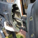
- The red arrow shows the location of the shift rod connector, on the inboard side of the motor. The area is sort of hidden by the hinge, so its better to tilt the motor back when working on this.
-
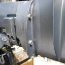
- These bolts hold the lower unit to the upper casing.
-
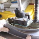
- The interior of the water pump, showing the impeller and gasket. The outer plate is behind the gasket already. The metal insert cartrigde goes over the impeller before the black housing is reinstalled.
-
- The water pump as assembled on the drive shaft.
-
- Carefully inserting the lower unit into the upper casing. The Drive shaft and shift rod are mating with the parts in the upper casing properly.
October 15th, 2010at 7:10 pm(#)
Thank you so much for going to the trouble of posting this. I have the exact same motor and having read your article will now have the confidence to have a go myself.
January 16th, 2011at 5:13 pm(#)
I wanted to say thank you as well. for taking the time to share the knowledge. Much appreciated. I just rebuilt my water pump on the same engine, thanks to you.
Cheers,
Mark
February 19th, 2011at 4:55 pm(#)
Thanks .this has been very helpful and Im attacking it now.
Thanks again.
March 5th, 2011at 1:55 pm(#)
Rally good help! Photos were extremely helpful! Thanks for taking the time.
September 3rd, 2011at 1:50 pm(#)
Great, thanks for this! Found this doing a Google search, didn’t know how shift linkage worked, I do now! 🙂
December 2nd, 2011at 5:35 pm(#)
Very helpfull, I found it easiest to push the shifter rod down into the gearcase, putting it into reverse, and having the gear shifter on the cowling into forward. With the lower unit attached, lining up the shift rod with the connector was easy, just put it into reverse at the cowling while guiding it into the connector.
February 1st, 2012at 3:36 am(#)
Cheers, you’ve no idea how much this post has helped me. I have just serviced my 2007 8HP and without this post I would have not been able to perform the task. Thank you heaps.
June 6th, 2012at 11:12 am(#)
Loads of thanks,
I could’t find that nut (actually it was at the other end of my spanner !)to take apart the two bits of the shift. Nearly put the engine into pieces and then I came across your site & snaps. God, (not you) that was it.
Very handy indeed.
Louis V
July 12th, 2012at 5:47 am(#)
Thanks for this — very helpful — i am in the process of reassembling a 5 hp after water pump replacement and all i have left to do is connect the shift rod clamp — i can see exactly what i need to do but the opening is small and i cant get my fingers in there to manipulate the clamp — tried a needle nose with no luck….any tricks/tools to get the clamp back in position and then to tighten??
July 27th, 2012at 11:36 pm(#)
Thank you for bothering to do this.
I have the same issue of no water from the cooling exit hole and suspect everything is blocked up like yours.
I will now with confidence take the motor apart and see what I find!
Thanks again
September 24th, 2012at 3:35 pm(#)
Super helpful. Ran out of daylight, but thanks to your instructions we were able to complete the install in 20 minutes. Many thanks.
August 3rd, 2013at 5:07 pm(#)
Thanks for this detailed post. I did this job today without benefit of this wisdom. However, I am stuck re-seating the lower unit. Even skipping connecting the shift cable, I can’t push the two pieces toegether. It seems as if the drive shaft won’t seat up in the engine. I have about and inch or so gap. Is there a trick here? Perhaps a reverse or forward option? Any tips and suggestions would be greatly appreciated.
Many thanks,
Keith
August 23rd, 2014at 11:53 pm(#)
Many thanks for your detailed outline of water pump replacement. You’ve equipped me with the confidence to proceed knowing that I’m not going to do damage.
Best wishes,
Garth
March 19th, 2016at 2:37 pm(#)
Hi guys,
Much appreciated instructions for salty old job. I did all this ten hrs 5 yes ago and flushed every time but it has clogged again.
Thanks for the quality article.Well. written.
Ch were
Byron
Wellington
New Zealand