Rebuilding the rudder
October 23rd, 2013 | by Van | Published in Haul outs, Maintenance and Repairs | 4 Comments
One persistent theme on the Nicholson 38 community forum is the rudder. The rudder is hung off the back of the keel, has most of its weight supported by a shoe at the bottom, and a hinge in the middle just below the aperture for the propeller. The rudderstock is originally specified (according to the Nicholson 38 drawings provided by Jeremy Lines) as Manganese Bronze. It is 1.375 inches in diameter. It has a stuffing box above the deadwood, and is connected to the upper portion of the rudderstock by a steel collar with keyways in both parts. The Mathway steering and emergency tiller connect to this upper section.
What are the concerns?
Firstly, for Rainshadow, the rudderstock was stainless steel (in spite of the drawing). Therefore crevice corrosion is a concern. Secondly, the hinge and shoe may become dezincified and brittle. Thirdly, because of wear in the lower bushing, play develops in the movement, which can perhaps lead to sloppy steering, or vibration of the rudder at speed. Lastly, several owners found (or surveyors with moisture meters found) that the rudders had water in them.
Mostly because of the stainless steel rudderstock, we decided to rebuild the rudder. We chose to do this in Port Townsend, Washington, mainly because we knew that Pete Langley at Port Townsend Foundry was there and willing to help us. He’s really great to work with, knows an amazing amount, and does really nice work. He’s the one who made us a new white metal bearing in about 24 hours back in 2011. We also have had good experiences with the SEA Marine boatyard – they have fair prices, and an enthusiastic and helpful staff, and more importantly they welcome DIYers and do not object to having specialists like Pete come onto their site to do work.
Removing the rudder
The first task in removing the rudder was to have the shipwrights at SEA Marine cut the steel collar in half lengthwise. It had rusted onto both sections of the ruddershaft and could not be removed without destroying it. It took an hour and a half of cutting and hammering to remove it. Note, the upper section to which the steering arm is attached was free to fall downwards when the collar was removed. I tied it in place.
We removed the rudder by having SEA Marine lift Rainshadow in the travellift by about two feet. This allowed us to get at the two screws on the underside of the shoe as well as the six on the sides so we could remove the shoe. The hinge came off easily. The screws are all coated in resin, which was easy to knock off and chip out of the screw slots. Once the shoe and hinge were removed, the rudder easily dropped out of the boat (prop and shaft were removed earlier).
Dezincification of the shoe and hinge
In previous haulouts we scratch tested the shoe and hinge and were satisfied they were good. This time, the hinge was definitely questionable. I drilled test holes into the metal, about 1/16″ deep using 1/2″ bits to give a shallow but wide cut. This clearly showed the pink dezincification in the hinge. The shoe however was fine with only a minute pink surface layer.
So what is the purpose of the hinge? Interestingly, looking at the part of the rudder that the hinge wraps around, there was no evidence of wear. It was as if the hinge was barely touching the surface. That seems to imply its role as a backup support in case the shoe failed, for instance in a hard grounding it is conceivable the shoe would be torn off. The rudder would then be held in place by the hinge. Without the hinge, the rudder would drop until the collar slid down and landed on the stuffing box, about 6 inches. That in turn might disable the steering mechanism.
We had the hinge remade by Port Townsend Foundry and reused the shoe. As a side note, the forces on the shoe are primarily lateral, as when in the water, the rudder has nominally neutral buoyancy. (Rough calculation of the rudder volume is about 30 liters, or 30 kg of buoyancy, very close to the weight of 70 lbs = 33 kg).
Does the rudder have water in it, and if so, does that matter?
The weight of the rudder when I took it off the boat, was 76 pounds. After rebuilding, it was 69 pounds. So that suggests I probably removed about a gallon of water. Most of the foam was damp, but only saturated at the bottom near the shoe, and at the entrance of the rudderstock. The water was heavily contaminated with copper and was acidic – it turned all my steel tools (like scrapers) a pretty copper color. That copper must have come from the bottom paint – the copper was able to diffuse through the 0.25 inches of fiberglass into the interior. If copper ions can migrate like that, then for sure water can. That means the rudder takes on water through its skin, not only through holes in the skin. I guess that’s just the way polyester resins from the 70s are.
How important is play in the rudder?
There are two primary “plays” to consider: the movement of the rudder relative to the rudderstock (ideally there would be none); and movement of the bottom of the rudder relative to the “shoe”.
Does play between the rudder and rudderstock matter?
Given the differences between a metal and polyester resin, it is inevitable that the bond between the two will eventually fail, and water will get in between. However, the movement of the rudder does not depend on this bond, rather it is the rudderstock pressing against the fiberglass that makes the rudder move. As long as the fiberglass is strong, I don’t see what difference a failed bond would make. The play that we observed was a barely discernable movement between the metal and the goop (mostly bottom paint) where the stock enters the rudder. The play in the steering system is much, much larger, so functionally this play has no effect. The failed bond does provide a way for water to get into the rudder, but as noted elsewhere, water will get in anyway. So my conclusion is that this play is inconsequential.
Does play at the shoe matter?
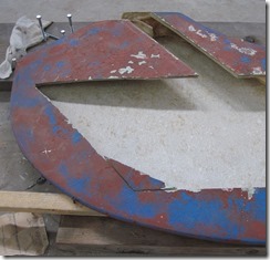
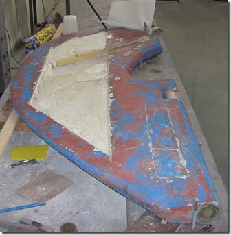
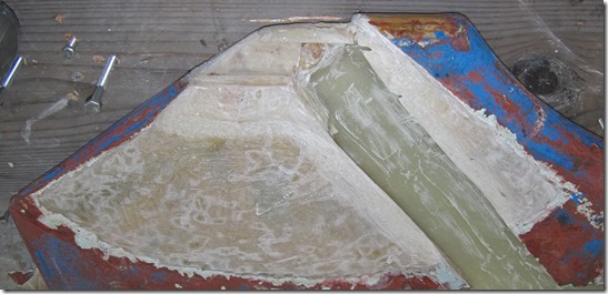
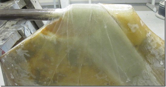
The play at the bottom of the rudder, where it is held by the shoe was quite large – the bottom of the rudder could be moved almost 0.25″ from side to side. The shoe has a pin (approx 0.5″ diameter) that points up , and the rudder has a hat shaped bearing that sits over the pin (see photo right) – this bearing is glued into a plastic receptacle in the base of the rudder (see photo left).
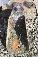
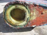
Over time, the bearing had worn significantly (while the pin in the shoe had not). This kind of movement has a couple of effects. Firstly, it places a torque on the log and stuffing box. This is likely to make the stuffing box leak more and cause faster wear in the log. (I don’t know what the log is made out of, as I did not get a good look at it.) Secondly, we have noticed that the rudder “flutters” under some conditions, typically at higher speeds. It manifests itself as a vibration at the wheel. This might be caused by excessive play – we’ll be watching for this in next year’s sailing to see if it still happens. [Update 2015: the flutter is gone with the new rudder and bearing.] Or, it may just be a feature of the water flow past the rudder creating vortices that cause the vibration. In any case, this does not seem to be more than an inconvenience unless it causes problems at the stuffing box.
Cutting the rudder apart
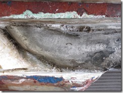
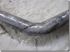
I chose to excise the rudder stock by cutting a slot into the rudder where I knew (from exploratory holes) the stock was. Using a multi-tool (oscillating tool) with a carbide blade, I cut the starboard face – a fortunate thing as the stock had been glassed to the starboard side only. This meant I could remove the stock with a piece of the surface skin, leaving a channel. The first picture shows the channel cut at the bend in the rudderstock, just to the left of where the stock enters the rudder. The second picture shows the bend in the rudderstock, with the internal part lying to the left.
The old stock showed signs of heavy corrosion where the stock fits into the stuffing box, and near the area where it entered the rudder. Interestingly, the stock inside the rudder was pristine – no (visual) evidence of corrosion, it looked brand new. It was as if the copper laden, acidic water the metal was in somehow protected it. The worst corrosion by far was where the stock was in the stuffing box.
It was also clear that the bend in the stock was made by welding two pieces together, not by bending a single piece.
I then opened up several panels in the starboard face to get access to the foam inside. I removed the foam using various scrapers, etc. The foam was wet, but generally not saturated. Once clear of foam, I sanded down the internal faces of the skin and dried everything for several days using a fan and heater.
Note: I should have had the bottom paint sanded off before starting this, but impatience got the better of me. I had SEA Marine do this for me in the middle of the project – it took about four hours.
Replacing the foam
I used System Three Urethane expanding foam to fill the rudder in stages. This foam is closed cell, and can be poured onto cured foam. It was nominally 2 pounds per cubic foot density, although because I was working at lower temperatures (60 deg F vs the recommended 77) it probably has a higher density. I made dams around the area where the rudderstock would go using a rigid closed cell foam that SEA Marine had on hand. This kept the space for glassing down the stock clear. I screwed tabs onto the panels so that they would sit at the right height on top of the foam as it cured. The panels needed to be weighted down to prevent the foam lifting them (lead bricks are handy for this!). Once cured, the panels were well stuck down making it easy to grind a nice 2″ scarf along the seams.
The new rudderstock
Pete recommended getting Aluminum Nickel Bronze because of its high corrosion resistance and high strength (100,000 PSI vs 70,000 PSI for stainless steel). He also bent the new one to match the old stock so it would fit perfectly into the rudder. He then honed down the internal section to match the old one (see also the schematics on the Nic 38 Drawing CD from Jeremy Lines), and lastly machined a keyway. It cost $350 for the materials and another $350 for the labor, and it will outlast the boat. Thanks Pete.
Embedding the new rudderstock
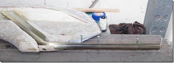
At Pete’s urging, I spent a lot of time figuring out how to make sure the rudderstock was accurately aligned with the shoe. He pointed out that an error in alignment would cause uneven wear and should be avoided. I built a jig on a table top using long screws surrounding the rudder to hold it in place. I used several lag screws embedded in the table to hold the rudderstock in position, and was able to accurately change the rudderstock alignment by screwing the lag screws in or out. To check the alignment, I stretched strings from one end to the other – this made it easy to visually check the alignment along both axes.
This picture shows the new rudderstock lying in position with the strings used to check alignment.
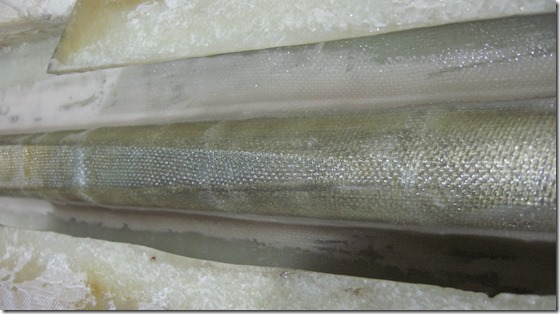
The first step was to build up the lower (port) side of the skin so that the rudderstock would sit on solid fiberglass at the right orientation and level. I did this with multiple layers of glass with System Three Epoxy. The new glass extended across about eight inches of the old skin. I then installed the new rudderstock, and after aligning it, embedded it in a generous filling of System Three Quick Fair. This is a system of epoxy and microballoons which mixes up into a mayonnaise like goop to be used for filling and fairing. The main purpose of the goop was to fair out the edge of the stock and make it easy for subsequent layers of glass tape and epoxy to be put down, avoiding strange or sharp angles. After this had set, I used more System Three Epoxy to lay many layers of glass tape over the stock until the thickness had built up to about the level of the upper skin. I wanted there to be no foam between the stock and the upper skin.
This picture shows the rudderstock after several layers of glass have been applied over it.
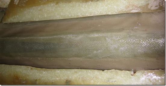
I filled up as much of the space between the rudderstock and the starboard side as I could with the fairing compound. I built up the fiberglass until it was level with the original skin. The next picture shows the stock starting to disappear under the layers of glass.
At the junction with the old skin, I scarfed the old skin and laid down multiple layers of fiberglass until the rudderstock was completely buried and the surface fair. Final fairing was done using the Quick Fair.
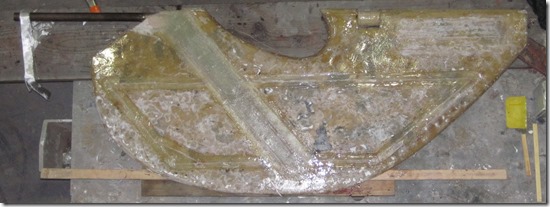
One of the areas of largest stress for the rudder is the area at the leading edge of the rudder where the rudderstock enters. This area had to be cut open to remove the old stock, and I was very concerned to get a strong, solid repair. To do this, I ground down the sides of the rudder just aft of the leading edge in such a way that I could “fan” out multiple layers of fiberglass. So, while each layer would pass over the rudderstock in the small region at the leading edge, the layers would spread out across a wide area of both sides of the rudder. The idea was to maximize the surface area in contact with the old rudder skin, and maximize the strength at the leading edge. Hard to describe, but it should be clear from the pictures.
For this stage of the glassing, I suspended the rudder from the rudderstock and foot between to saw horses, which allowed the body of the rudder to hang down. This made it possible to work both sides at once, running glass tape from one side to the other. After glassing the “fan” it looked like this:
Epoxy coating the rudder to reduce water absorption.
Once the stock was installed and the surfaces faired and sanded, I put three coats of System Three epoxy onto the rudder to reduce water absorption. This epoxy is (according to System Three) 100% waterproof if applied correctly, which means a minimum of two layers rolled on. I would have put on more layers but was running out of time. I finished with the bottom paint while the last coat was still tacky, to get a good bond.
Replacing the collar with a coupler
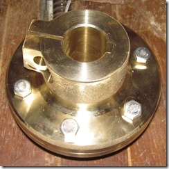
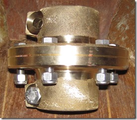
Pete suggested that rather than make another collar with the problems such a design has, it would make more sense to build a coupler. One part of the coupler clamps onto the upper stock, and one to the lower. Both share a common keyway to maintain alignment. They are bolted together using six bolts. Once installed, it looked bombproof.
Very clever design by PT Foundry.
Installing the rudder
Installation was the reverse of removing it, and went smoothly. SEA Marine picked up Rainshadow and left her in the travellift in the afternoon on Friday, leaving me the whole weekend to work on her if need be. Having a boatyard that would work with me like that was a huge benefit. And Gus, their travellift operator was enormously flexible with his weekend, by offering to come in when ever I was ready – which turned out to be Saturday afternoon.
I installed the rudder myself as it was late Friday and I was hoping to splash on Saturday. I picked it up and shoved the stock into the hole, and jacked up the rudder with wood blocks, leaving enough room to get at the shoe and bearing. Once the shoe was in place, the blocks could be removed. The biggest delay was me failing to assemble the stuffing box correctly, and having to drop the rudder again to start over.
The hinge was a bit awkward – it must be on the rudder but splayed out so that it fits over the keel as you slide the rudder up. Once the rudder is in place, the hinge must be bent to the correct shape. It was possible to get a long jawed clamp to span the hinge from inside the aperture, and this made it straightforward to force the hinge closed. Pete and I had decided to clamp the hinge in place using through bolts instead of the original machine screws in the fiberglass keel. He made holes in the starboard side of the hinge to match the original holes. I then drilled the original (starboard) holes through the keel to the other side. Only later did I realize that of course these did not align very well with the original holes on the port side. In any case, the through bolts worked. They are Silicon Bronze and I cut them off with a few threads above the nuts, and then peened (hammered) the threads down to lock the nuts in place.
The coupler worked perfectly and was easily installed.
Saturday afternoon we splashed, and Sunday I motored back to our slip 15 miles away. Everything worked, but only time will tell if the rebuild was successful.
UPDATE: 2022
I forgot to mention that I added a hole in the trailing edge of the rudder as far aft as possible, about 1/2 inch diameter and close to the edge. The purpose of this, is that in the event of a catastrophic steering failure, we will be able pass a line through this hole (with stopper knots on either side of the hole) and back to the cockpit, where we can jury rig a way to move the prop. I suppose a really salty sailor will already have this line rigged and ready! 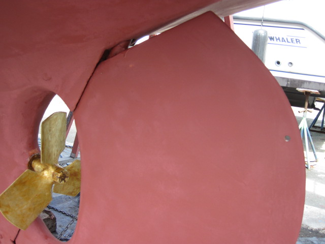
November 3rd, 2013at 6:56 pm(#)
Hello Van,
Thank you for sharing this comprehensive and nicely photographed rudder rebuild project.
My Nic 38 (hull #99) has a bronze (manganese bronze???)rudder stock (prop shaft is same). Now that I know what to look for I can do some “exploratory surgery” with minimal collateral damage.
For some time I have wondered how the shaft is fixed to the rudder internally… now I know. I had thought it must be more complicated than a simple bend in the shaft.
Thanks again,
Fred
June 18th, 2017at 5:44 am(#)
Van,
Very interesting article, we have used it a lot in our rudder re-build.
I note that you had to replace the hinge strap. We too have dezincification and the hinge strap cracked when we opened it up to drop the rudder.
Can you remember what material you used to make the new one? We are having problems obtaining DZR Brass, which is what we assumed the old strap was made from.
David
June 24th, 2017at 3:18 pm(#)
David – we looked at our notes and can find no information on what material was used to build the new hinge strap. However, our recollection was that it was Bronze, not DZR Brass. We just don’t know what kind of bronze. Sorry not more help.
Marilyn and Van
July 3rd, 2017at 3:54 am(#)
Thanks Marilyn, we have replaced ours with marine grade Phosphor Bronze (PB102), DZR brass seems to be no longer available in the UK as flat bar. We will do a report on our rudder re-build for the web site idc. David